Braided Shields
Coupling Through Braided Shields With Ideal And Non-ideal Geometries
By Jennifer Kitaygorsky and Anthony Supino
Coupling through braided shields is determined by the transfer impedance, an intrinsic property of all cable shields. Here, we compare transfer impedance measurements of braided shields and various cables with ideal (round) and non-ideal (flattened) geometries.
Numerical modeling techniques of EMI coupling to cables and connectors are used frequently in various design and certification processes. For example, part of the aircraft FAA certification requires that coupled currents and voltages on pin wires of harnesses due to a lightning strike are below the avionics circuits specification levels. Numerical predictions of these coupled pin transients greatly reduce the design and certification costs.
An avionics cable harness assembly might look like this:
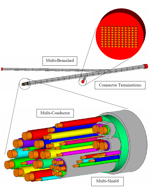
Note the idealized geometry. In most cases, however, the shields and overbraids are not perfectly round, but usually flattened depending on the respective sizes of the ovebraid and its contents. However, because there are capacitance and inductance matrices associated with the various cable geometries, having a flattened overbraid (instead of a round one) will change those parameters. Furthermore, because most shields are braided, there are aperture and porpoising coupling mechanisms associated with the braided shields, which can also be affected by the shield/overbraid geometries. In most cases, the cable harness assemblies are not available for a thorough evaluation of the capacitance and inductance matrices, as well as various coupling mechanisms, and the modeler has to be content with the idealized geometries as inputs in the model due to their relative simplicity.
A real harness cross section might look like this:

A braided shield/overbraid has three chief coupling mechanisms:
- Diffusion (resistive term, dominant at lower frequencies)
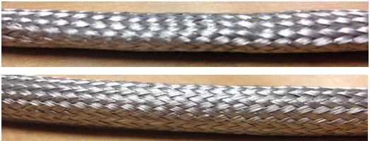
- Aperture (inductive term, dominant at high frequencies, note the diamond-shaped holes in the overbraid pictured above)
- Porpoising (additive term at high frequencies, due to contact resistance between individual carriers)
These coupling mechanisms are encompassed in a quantity called transfer impedance, which is one of the model input parameters. To learn how the transfer impedance depends on the shape of an overbraid, we constructed several cable measurements, summarized below.
Measurement # | Description |
1 | Wire inside flat overbraid |
2 | Wire inside round overbraid |
3 | Twisted pair inside flat overbraid |
4 | Twisted pair inside round overbraid |
5 | Twisted shielded pair (TSP) inside flat overbraid |
6 | Twisted shielded pair (TSP) inside round overbraid |
7 | Twisted shielded triplet (TST) inside flat overbraid |
8 | Twisted shielded triplet (TST) inside round overbraid |
Note the additional shielding for measurements 5-8, which are made with twisted shielded pairs or triplets. The tests were performed on 1 m long cables above a copper ground plane, using a current injection probe and a network analyzer. The same type of overbraid was used for all measurements and the term ‘flat’ simply means that the overbraid is larger than its contents and therefore tends to flatten. For the ’round’ overbraid, spacers were added so that the cable tends to stay consistently round. The voltage was measured on pin wires and divided by the overbraid current to obtain transfer impedance Zt. The results are shown below.
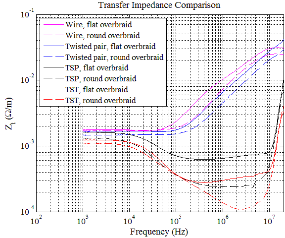
The spread of Zt values at low frequencies, which is less than 500 μΩ, is likely due to the differences in contact resistance of overbraid to connector. For tests 1-4, diffusion dominates below ~ 100 kHz. For tests 5-8, because of the double shielding, diffusion dominates below ~2 MHz, a decade of difference. Also note that Zt is much lower in double-shielded cables in the frequency range of 20 kHz – 20 MHz by up to three orders of magnitude, making double shielding quite advantageous.
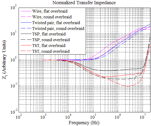
Consistently, the round overbraids perform better (lower Zt) when the aperture coupling starts to take effect above around 100 kHz. The spread of Zt values at low frequencies make this difficult to see, so we normalize the transfer impedance curves to the values at 1 kHz, shown below. The difference in Zt due to the shape of the overbraid can be as high as 40%.
It is easy to see why the coupling is higher for the flat overbraids. In the picture below a flattened overbraid is shown, while a round overbraid is shown in the one below that. The apertures of the round overbraid are consistent in size and angle, while in the flattened overbraid, the aperture size and angle changes at the edges, making it a looser weave susceptible to having larger apertures.